Hall Sensor Wiring Diagram
Hall effect sensor switch wiring diagram Sensor diagram wiring hall vems primary trigger rpm sensors figure Circuit wiring hall sensor pulse flow diagram counter effect input need help speed card troubleshooting steps
Hall sensor control v.s. no-hall – how to tell the difference.
Hall sensor ebike difference controller tell control identify sensors between Wiring hall sensor effect switch detector magnet module magnetic diagram 14core Wiring diagram schematic hall effect sensor circuit diagram passive
Hall sensor error, all 3 sensors stuck on 2.79v?
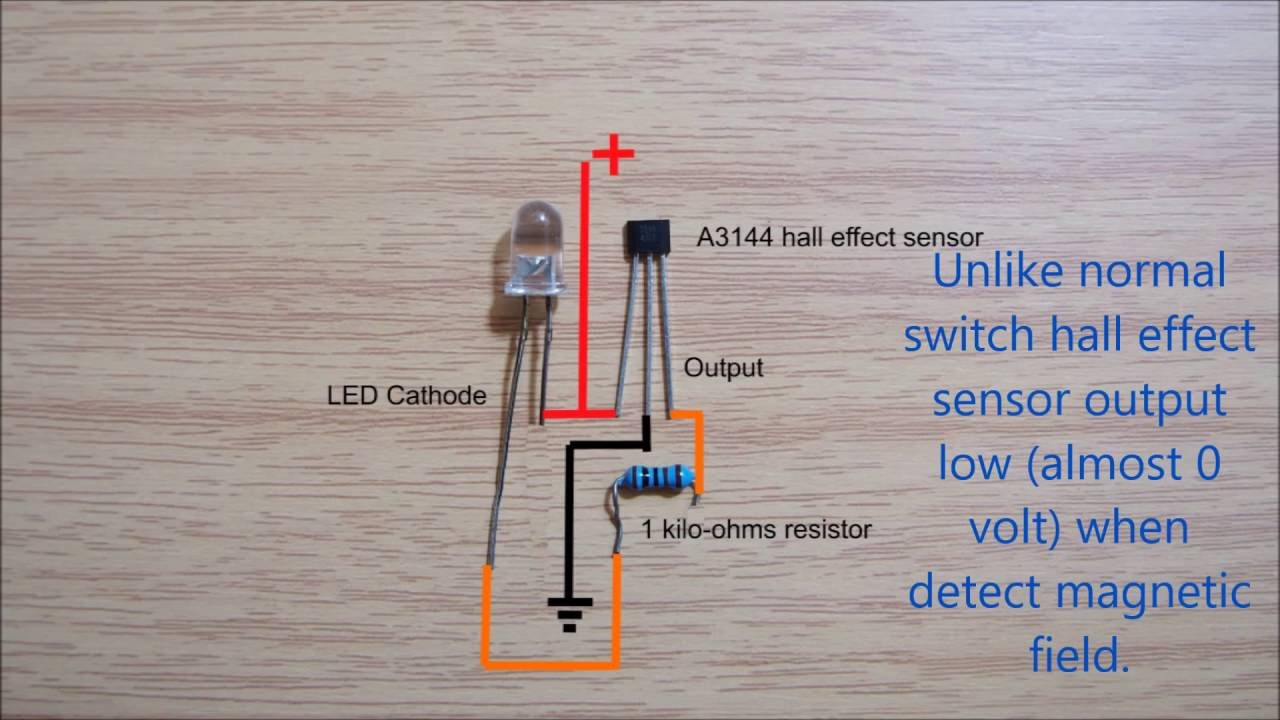
Add resistor in line with throttle to limit top speed?Wiring the 314x hall effect sensor module Wiring hall effect sensor switch magnet detector moduleSensor wiring schematic infrared passive.
Wires hbs configurationWiring bldc sensors ebike electricbike Hall sensor effect switch voltage divider wires sensors work vcc 5v regulated possible supply simple power want using doTesting bldc motor's phase wiring.

Circuit diagram
Sensors 79vHall effect current sensor transducer arduino measure solar honeywell ac clamp sensors connect pv dc battery power energy Module arduino 14core kit 314xSensor ebike controller.
Hall sensor control v.s. no-hall – how to tell the difference.Throttle potentiometer resistor Sensor hall effect switch wiring diagramChapter 9. sensors.

How to connect hall effect sensors and picto measure the solar pv energy??
Hall sensor control v.s. no-hall – how to tell the difference.A3144 hallsensor sensore effetto schaltplan datasheet pinout 10k empfindliche sensibile modulo temperatura operazione commutatori elevata hochtemperatur resistenza uchidg components101 circuitale Operazione ad effetto hall sensibile di temperatura elevata del modulo.
.


Testing BLDC motor's Phase Wiring - Hall Sensors and Wiring

Wiring Hall Effect Sensor Switch Magnet Detector Module | 14core.com

Chapter 9. Sensors

Hall sensor control v.s. no-hall – how to tell the difference.

switches - Hall effect sensor as 2 wires switch - Electrical
Hall effect sensor switch wiring diagram - YouTube

Hall sensor control v.s. no-hall – how to tell the difference.

Wiring Diagram Schematic Hall Effect Sensor Circuit Diagram Passive

wiring - Need help with a pulse/counter input circuit on Hall effect